Design and Fabrication of 6DOF Cobot
Motivation
I have always wanted my own Cobot, or Collaborate Robotic Arm, for personal projects. Unfortunately, most robots available to purchase are either tens of thousands of dollars or are educational toys incapable of handling any serious payload. With a budget of $1000 and access to my school’s machine shop my goal was to design and fabricate my own Cobot from scratch. Despite low reduction, this robot with 0.7m reach is capable of supporting a 5kg payload
Design Objectives:
6DOF
Backdrivable (meaning very low joint friction)
0.65m reach
5kg max payload
BOM < $1000
< 0.5° backlash
Manufacturable with 3D printing/ waterjet/ Bridgeport Mill
Safe for use in contact with human users
Motor Selection
One of the most important design decisions when building a robotic arm is the choice of motor for each joint. Mass, torque, speed, size, cost, and mounting hardware must all be considered. When motors are fixed to moving links rather than grounded at the base, placement of a motor can have just as large an effect on the “inertia budget” as the mass of the motor. Because high speed and position accuracy are required for this build, I chose to use 3 Phase Brushless DC (BLDC) motors rather than steppers or simple brushed DC motors. All motors are controlled via torque control using the popular ODrive BLDC driver boards.
When constructing a robot with the goal of maximizing backdrivability, it is generally desired to have as small of a speed reduction as possible at each joint due to the linear relationship between speed reduction and friction in a mechanism. Unfortunately, this means that the robot requires the use of “hotter” motors that draw more current at a lower voltage which leads to a lot of lost energy through I^2*V losses.
By far the motors with the best torque to price ratio are “hoverboard” wheel hub motors which can be found for as little as $20 on Ebay. With a torque constant, (aka Kv value) of 16 they are capable of outputting over 10 Nm of torque at 20A. Unfortunately, they are over 3 kg each so they are only usable very close to the base of the robot.
I found that the next best choice of motor for joints where weight was an important factor were Turnigy “T-Motors” often found on heavy lift drones and other multicopters. With a less ideal Kv value of 100 and a price tag of around $80 these are not as cost effective as the trusty hub motors but their light weight makes them a better fit for moving joints. Additionally, the lower impedance of the T-Motors allow for a significantly higher current control bandwidth.

One early prototype of the robot used the heavy hoverboard motor as a counterbalance to cancel out some of the mass of the upper arm
Speed Reduction
Following motor selection, the next most important factor in the design is the choice of speed reduction. Initial prototypes used automotive timing belts to provide large reduction ratios and move motors closer to the base of the robot to improve inertia, however, belt slipping proved to be enough of a problem to avoid this type of strategy in subsequent prototypes.
Many industrial arms such as Universal Robots UR5 use Strain-Wave gearboxes, however, these require ratios of 50:1 or greater and were therefore not considered for this project. A similar design known as a hypocycloidal gearbox offers similar benefits in zero backlash, high strength and compact size with reduction ratios as low as 10:1. Unfortunately, even the cheapest of off the shelf hypocycloidal reducers cost hundreds of dollars so I had to resort to building my own.
After a considerable amount of trial and error I was able to model a single stage 10:1 unit in Inventor.


Once the design was verified on a quick laser cut/ 3DP prototype it was time to move to the CNC

Unfortunately, the friction in my hypocycloidal gearbox was high enough to prevent the reducer from being backdriven so this idea was put aside for now. The next design I tried out was a single stage planetary gearbox.

Gearboxes were designed using Autodesk Inventor’s gear generation tool and printed in ABS. Ultimately, I found a 9:1 reduction best for joints 1 and 2 and a 6:1 best for the third joint. Helical teeth were chosen for noise reduction.
BOM for internal and external bearings were copied from Gabrael Levine’s OpenTorque Actuator project thanks to his work finding the most cost efficient hardware for a DIY gearbox of this scale. After arriving at tooth designs I was happy with I made a housing that could be adapted slightly to work for the three different joints in my robot. Even though the current iteration of this robot uses planetary gearboxes, it is likely that I will ultimately go back and iterate on my previous hypocycloid design to reduce friction. In order to make it easier to go between different reduction mechanisms, all of the gearboxes in this design are self-contained modules that can be easily swapped out for future design iterations.


For joints 4, 5 and 6 I was able to use the existing GearDownForWhat open source 5:1 planetary gearbox, only modifying the sun gears to mount to the T-Motors. Speed reducer design for these joints is far easier due to smaller moments acting on the lower arm.

Link and Bearing Design
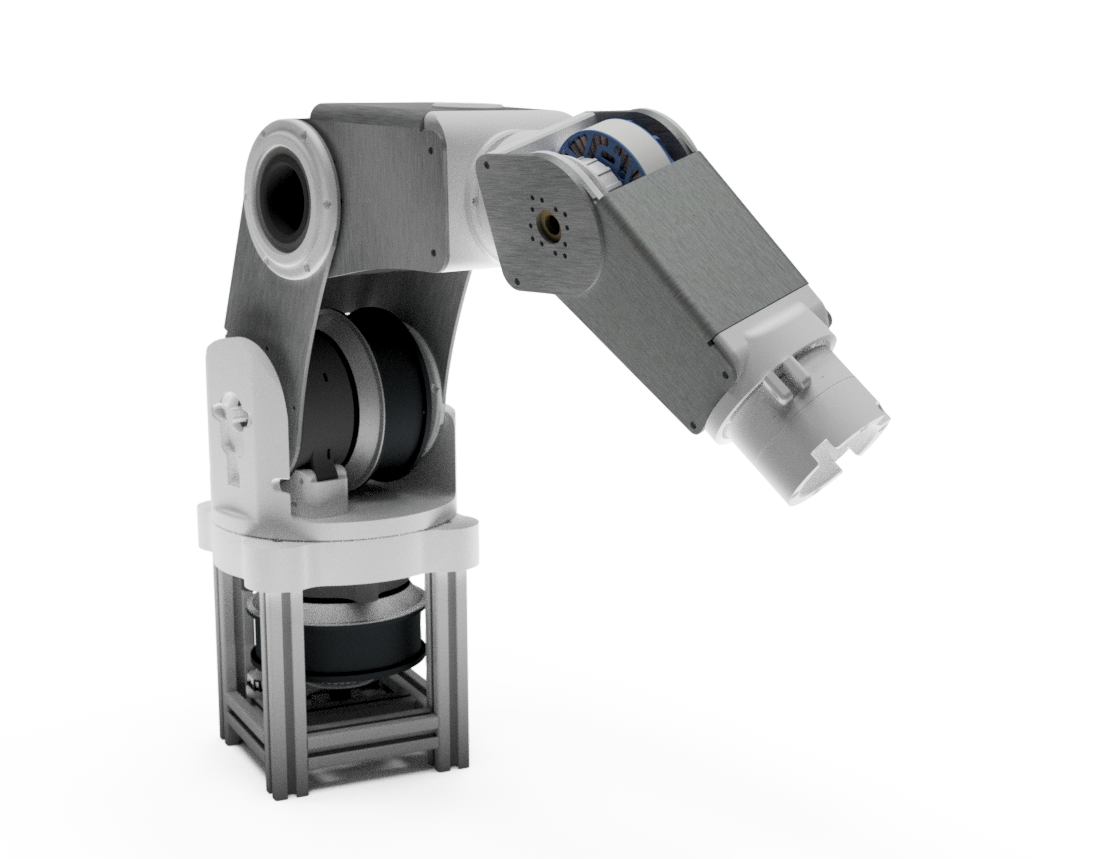
Visually, the most distinct aspect of this robot is the unibody sheet metal construction. This “hard shell taco” shape for each link was chosen to maximize stiffness while keeping the BOM as simple as possible. Previous iterations used parallel sheets of aluminum sandwiching turned spacers, however, this made disassembly difficult and allowed the frame to twist excessively.
The high current requirements of the motors in this design made it difficult to find suitable slip rings for central cable routing, so motor phase and encoder wires were routed inside the main links and wrapped around joint 4 similar to the brake lines on a bmx bike. This allows more than 360° rotation and keeps the cables relatively organized.
Demo of the robot moving through a series of position targets using PID control